2726
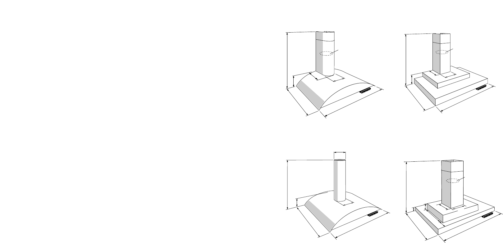
Auf der vorigen Seite sind die wichtigsten
Maße angegeben. Sie können die Höhe des
Teleskoprohres einstellen. Beachten Sie
jedoch die erlaubten Abweichungen.
Befestigen Sie den Abluftstutzen und den
elektrischen Anschluß so, daß Sie sie später
einfach an die Dunstabzugshaube
anschließen können.
Teleskoprohre aufhängen
- Bestimmen Sie die Länge des
Teleskoprohres. Beachten Sie die
erforderliche Mindesthöhe über der
Anrichte.
- Schieben Sie die beiden Teile ineinander.
Bringen Sie das Teleskoprohr auf die
richtige Höhe.
- Bohren Sie die Befestigungslöcher
(3,7 mm) 4x.
- Setzen Sie die Teile ineinander mit den
Schrauben.
- Markieren Sie die Löcher für die
Befestigung an der Decke mit Hilfe der
Schlabone.
- Befestigen Sie die Dübel, Schrauben und
Gewindestücke an der Decke.
- Bringen Sie die Drahtstangen auf die
richtige Länge. L = Länge Teleskoprohr +
20 mm.
- Schrauben Sie die Drahtstangen in die
Gewindestücke an der Decke.
- Bringen Sie das Auschlußkabel und den
Abluftschlauch an.
- Schieben Sie das Teleskoprohr über die
Drahtstangen und befestigen Sie das
Teleskoprohr mit den beigefügten
Muttern.
Motor befestigen*
*Nur für Geräte mit integriertem Motor.
- Schrauben Sie den Motor mit drei
Schrauben und Federringe in das untere
Teleskoprohr.
- Wenn der Motor extern ist, die 3
Schrauben und Federringe in die
Befestigungslöcher des Motors drehen.
Montage der Haube
- Befestigen Sie die Dunsthaube mit Hilfe
der Muttern, Ringe, langen
Inbusschrauben und Federringen.
Steckerverbindungen
- Stellen Sie die erforderlichen
Steckerverbindungen her.
- Setzen Sie die Filter ein.
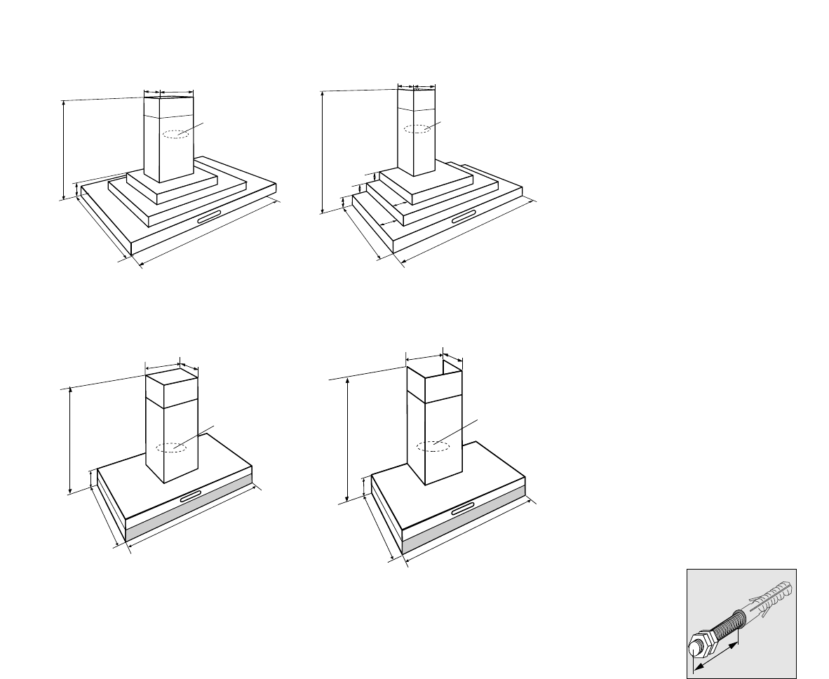
Einbau Wandmodel
Auf der vorigen Seite sind die wichtigsten
Maße angegeben. Sie können die Höhe des
Teleskoprohres einstellen. Beachten Sie
jedoch die erlaubten Abweichungen.
Befestigen Sie den Abluftstutzen und den
elektrischen Anschluß so, daß Sie sie später
einfach an die Dunstabzugshaube anschließen
können.
Markieren
- Zeichnen Sie die Mittellinie an der Wand.
- Markieren Sie die Bohrlöcher für den
Oberteil des Teleskoprohres mit Hilfe der
Schablone.
- Markieren Sie die Bohrlöcher für den
Unterteil des Teleskoprohres und die
Haube mit Hilfe der Schablone.
- Bohren Sie die Löcher ø 10.
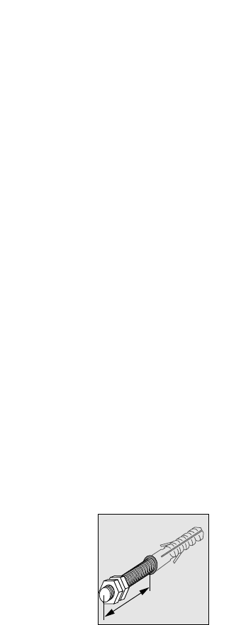
- Montieren Sie die Dübel und
Stockschrauben. Schrauben Sie die
Stockschrauben 20 mm in die Dübel ein.
Teleskoprohre aufhängen
- Befestigen Sie den Oberteil des
Teleskoprohres. Drehen Sie die untere
Mutter halb ein.
- Bringen Sie das Auschlußkabel und den
Abluftschlauch an.
- Schieben Sie den Unterteil des
Teleskoprohres hinter den Oberteil des
Teleskoprohres.
- Befestigen Sie die Teleskoprohre
vollständig.
Motor befestigen*
*gilt nur für Dunsthauben mit Einbaumotor.
- Schrauben Sie den Motor mit drei
Schrauben und Federringe in das untere
Teleskoprohr.
- Wenn der Motor extern ist, die
3 Schrauben und Federringe in die
Befestigungslöcher des Motors drehen.
Montage der Haube
- Hängen Sie die Haube über die
Stockschrauben.
- Befestigen Sie die Haube mit den Muttern
und Ringen.
- Befestigen Sie die Haube an die
Teleskoprohre mit Hilfe der langen
Inbusschrauben und Federringe.
- Lösen Sie die Muttern ein wenig. Drücken
Sie die Haube an der Wandseite so weit
wie möglich nach oben und ziehen Sie die
Muttern kräftig an.
Steckerverbindungen
- Stellen Sie die erforderlichen
Steckerverbindungen her.