459103
22
Zoom out
Zoom in
Previous page
1/50
Next page
EG
I
F
D
OPERATING INSTRUCTIONS
ISTRUZIONI D'USO
NOTICE D’UTILISATION
BEDIENUNGSANLEITUNG
INSTRUCCIONES DE USO
INSTRUCÇÕES DE FUNCIONAMENTO
MOVABLE AIR CONDITIONER with remote condenser
CLIMATIZZATORE PORTATILE
con condensatore remoto
CLIMATISEUR MOBILE avec condenseur a air extérieur
MOBILES KLIMAGERÄT mit Außenkondensator
AR CONDICIONADO com condensador remoto
E
37.4253.000.1 09/2004
P
DECLARATION OF CONFORMITY
This product is marked as it
satisfies Directives:
Low voltage no. 73/23 EEC and 93/68
EEC.
Electromagnetic compatibility no.
89/336 ECC, 92/31 EEC and 93/68
EEC.
This declaration will become void in
case of of misusage and/or non
observance though partial of
manufacturer's installation and/or
operating instructions.
Operating limits:
2
PRODUCT IDENTIFICATION
CONTROL PANEL
01. Control panel
02. Supply air deflector
, 3. Transportation handle (both sides)
04. Return air grille
05. Transportation wheels
06. Outdoor unit
07. Flexible tube
8. Handle (for transportation and hanging)
09. Air filter
10. Electric cable with plug
11. Outdoor unit hanger
12. Service tube for condensate evacuation
13. Outdoor unit basket or support
CONTENTS
PRODUCT IDENTIFICATION..............................................................................2
CONTROL PANEL ..............................................................................................2
BEFORE USING THE APPLIANCE ....................................................................3
AIR CONDITIONER INSTALLATION ..................................................................4
OPERATION
Cooling ......................................................................................................5
Fan only .................................................................................................... 5
SETTING AIR FLOW DIRECTION .....................................................................5
ACCESSORIES (SUPPLIED ON REQUEST) .................................................... 6
Air clean filter ...........................................................................................6
Supplementary basket or support guide kit for outdoor unit.................... 6
CARE AND CLEANING ...................................................................................... 7
USEFUL ADVICE ............................................................................................... 7
Room Temperature: Outdoor Temperature:
MIN: 15° C D.B. / 12° C W.B. MIN: 15° C D.B.
MAX: 32° C D.B. / 23° C W.B. MAX: 46° C D.B.
12
5
4
2
9
6
3
1
7
8
11
13
10
BASKET
SUPPORT
1. ON/OFF Push-button switch
2. Cooling push-button
3. High / Low fan speed push-button
4. Electronic thermostat Knob
5. Cooling lamp
6. High fan speed lamp
7. Low fan speed lamp
8. WATER LEVEL ALARM (RED)
It lights-on in case of misfunctioning of condensate evacuation system
.
9. Control panel cover
10. Supply air deflector in vertical position
10
8
7
6
1
5
2
3
4
9
EG
3
BEFORE USING THE APPLIANCE
Check that the power supply at the location where the air conditio-
ner is going to be used is 220-240V ~ 50Hz
Make sure that the electrical installation is suitable to supply conti-
nuosly current necessary for the air conditioner in addition to that
already used by other electric appliances (white goods, lighting).
See the max electric imput indicated on the name plate positioned
on the air conditioner.
The installation of a double-pole switch, protected by 10 A fuses of
the delayed type, upstream the electricity wall soket, is recommen-
ded.
The unit has to be connected according to the local electrical rules.
Make sure that circuit breakers, fuses, etc, are of sufficient capa-
city to handle a start-up current of 35 A (generally less then 1
second).
Do not install the air conditioner where it could be wetted by drops
of water (i.e. in laundries).
Make sure that the ON - OFF push-button switch on the control
panel of the air conditioner is in OFF position.
Before connecting the air conditioner to a power socket, make sure
that the socket is provided with an earth connection in compliance
with local codes.
Never use the power plug as a mean to start or stop the air condi-
tioner: always use the ON/OFF push-button switch on the air con-
ditioner control panel.
WARNING!
Do not stick anything into the air outlet of the air conditioner.
This is very dangerous because the fan is rotating at high speed.
WARNING!
The air conditioner is provided with a time-guard system, which
does not allow re-starting of compressor until after 3 minutes from
a previous stop. So avoid quick movements of the thermostat knob
in both directions when compressor is running.
Make sure that there are no obstacles around the indoor unit affec-
ting the free circulation of air. Do not block the air intake and outlet
of the unit with curtains or other.Never put objects on the top of the
unit.
The manufacturer assumes no responsabilities if the safety regula-
tions or local codes are not observed.
IMPORTANT ADVICE
1.When you move the air conditioner around your house, hang the
outdoor unit to the rear of the indoor unit. Be careful not to twist nor
kink the flexible tube.
2.When you move the outdoor unit, always hold it by the handle,
never pull it by the flexible tube.
3.Never let the outdoor unit hang on the flexible tube.
4.When you recover the outdoor unit after operation, drain away any
remaining condensate by tilting the unit.
EG
Always unplug the unit from the power socket before moving or clea-
ning it.
Some edges and the condenser fins are sharp and may cause injury
if handled improperly; special care should be taken when you clean
these parts.
WARNING
LIMIT OF ELEVATION
DIFFERENCE
1000
INDOOR UNIT
NO!
NO!
4
POSITIONING OF OUTDOOR UNIT
The outdoor unit must always be kept in vertical position
and levelled. Make sure that there are no obstacles around
the unit affecting the free circulation of air. A lug at the rear
bottom of the unit ensures the minimum distance from the
wall (3 cm). The unit must be kept at a minimum distance of
cm. 15 (sidewise) and cm. 80 (frontally) from any walls.
INSTALLATION TYPE A
If your room has a balcony or a window-sill of sufficient
depth (min. 25 cm) you may rest the unit freely onto it. For
safety’s sake, you may anchor the unit to the window-sill
using one M6 x 20 expansion bolt in the slot of the lug at the
rear bottom of the unit.
The flexible tube may easily pass through the balcony door
or window shutters set ajar.
INSTALLATION TYPE B (USING THE BASKET)
1. Fix the basket to the wall below the window sill.
2. Place the unit in the basket and check that it is levelled.
INSTALLATION TYPE C (USING THE SUPPORT)
1. Fix the support guide to the wall below the window sill.
2. Insert the support in the handle of outdoor unit, and turn
the outdoor unit upside down as shown in the picture.
3. Place the support and secure it at the edge of the unit,
using the screws.
4. Insert the support, fixed on the unit, at the guide fixed to
the wall. Make sure it is levelled.
EG
2 holes ø 10
SUPPORT
2 holes ø 10
support
guide
200
210
1
0
0
m
in
.
2
0
0
1
4
0
50
The air conditioner is made of two units interconnected by a
flexible tube. The indoor unit, movable on wheels, must be
placed in the room to be air conditioned, near a window, a
balcony-door or a perimeter wall. The outdoor unit, that pro-
vides to the disposal of heat and condensation, must be
located outside, on a window sill, on a balcony or hanged to
the wall.
Min. 25 cm.
BASKET
M6 x 20
M6 x 20
AIR CONDITIONER INSTALLATION
TYPE A
TYPE B
TYPE C
5
EG
For this operation the outdoor unit can be placed either outsi-
de(on the window sill or hanged to the wall) or inside, hanged
to the indoor unit.
The air conditioner is running in cooling mode.
Press the cooling push-button (2) to stop the compressor,
lamp (5) is relised (disactivated).
Select the fan speed pressing the fan speed push-button (3).
Starting the air conditioner in fan only mode.
Switch on the air conditioner pressing the ON/OFF push-but-
ton (1) .
Make sure that the lamp (5) is relised (disactivated).
Select the fan speed pressing the fan speed push-button (3).
FAN ONLY
To set the air flow direction, seize with both hands one of the
deflector blades and pull towards you.
Vertical Flow Horizontal Flow
OPERATION
SETTING AIR FLOW DIRECTION
8
7
6
1
5
2
3
4
Place the outdoor unit outside and insert the plug in the power
socket.
Twist the knob (4) of the thermostat to the right until you
reach the position of maximum cooling.
Switch on the air conditioner pressing the ON/OFF push-but-
ton (1) , lamps of last operations are displayed.
Select the cooling operation pressing the push-button
(2), lamp (5) lights.
Press the push-button (3) to select the high fan speed, the
lamp (6) lights.
When room temperature has reached the most suitable
value for your comfort, press again the push-button (3) to
select the low fan speed, the lamp (7) lights.
Now slowly twist the thermostat knob back towards the left
until the compressor stops. At this point the air conditioner is
set for automatic operation under the control of the electro-
nic thermostat to maintain the room temperature at the pre-
set value.
To stop the air conditioner press again the ON/OFF push-but-
ton. (1).
COOLING
6
EG
SUPPLEMENTARY BASKET OR SUPPORT GUIDE KIT FOR OUTDOOR UNIT
If you want to utilise the air conditioner in several rooms, it is possible to buy varies baskets or support guides for
the installation of outdoor unit.
Secure the “air clean filter” onto the standard filter by the
spring attached before in step 2.
3
Set the standard filter in the air conditioner with its
“FRONT” mark towards you and close the air intake grille.
Replacement of air clean filter
The air clean filter is disposable.
Do not throw away the filter frame and sping.
The used filter cannot be reused even after cleaning up.
Buy the air clean filter for replacement at your nearest
dealer.
Check the state of dirtiness at least once every two
weeks and replace the filter when it changes to be so
dirty as the color of the label “Color gauge for filter repla-
cement”.
4
“Air clean filter”
standard filter side: white
(dust collecting filter)
Spring side: black
(deodorizing filter)
standard filter
spring
2 holes ø 10
200
210
50
2 holes ø 10
support-
guide
1
0
0
m
in
.
2
0
0
ACCESSORIES (SUPPLIED ON REQUEST)
1.This carton box contains an air clean filter, a spring and
a label “Color gauge for filter replacement”.
2.Open the bag just before installing the air clean filter.
lf not, the deodorization effect durability of the filter may
be decreased.
AIR CLEAN FILTER
Read these instructions before starting replacement
work.
This “Air Clean Filter” collects dust as well as deodori-
zes.
NOTE
standard filter
air intake
grille
Filter installation procedure:
Open the air intake grille and remove the standard filter.
Stick the label “Color gauge for filter replacement” in an
easy-to-see postion (inside of control panel cover).
1
Attach the spring onto the standard filter:
Hook the spring onto the air filter from its rear side and
engage it into the groove on the “FRONT” mark side (use of
a standard screwdriver is recommeded fo easy setting).
2
standard
filter
spring
SUPPORT GUIDE
BASKET
CARE AND CLEANING
USEFUL ADVICE
WARNING! For safety’s sake, be sure to turn the air conditioner
OFF and also disconnect it from the power supply before clea-
ning it.
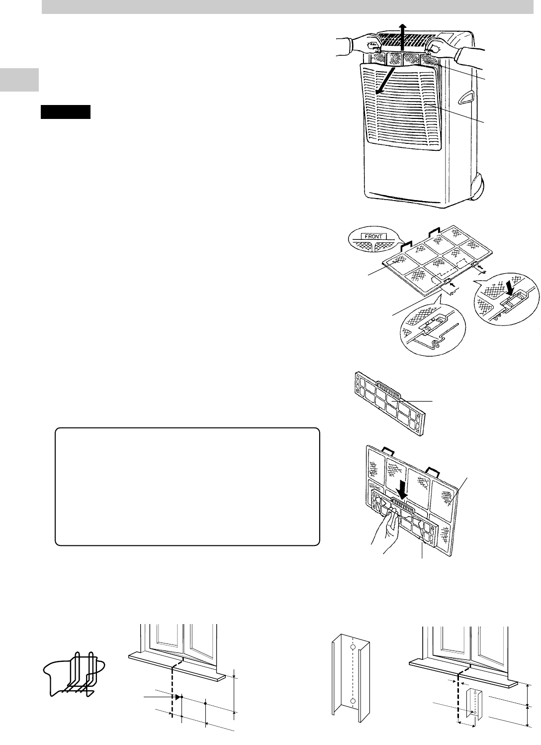
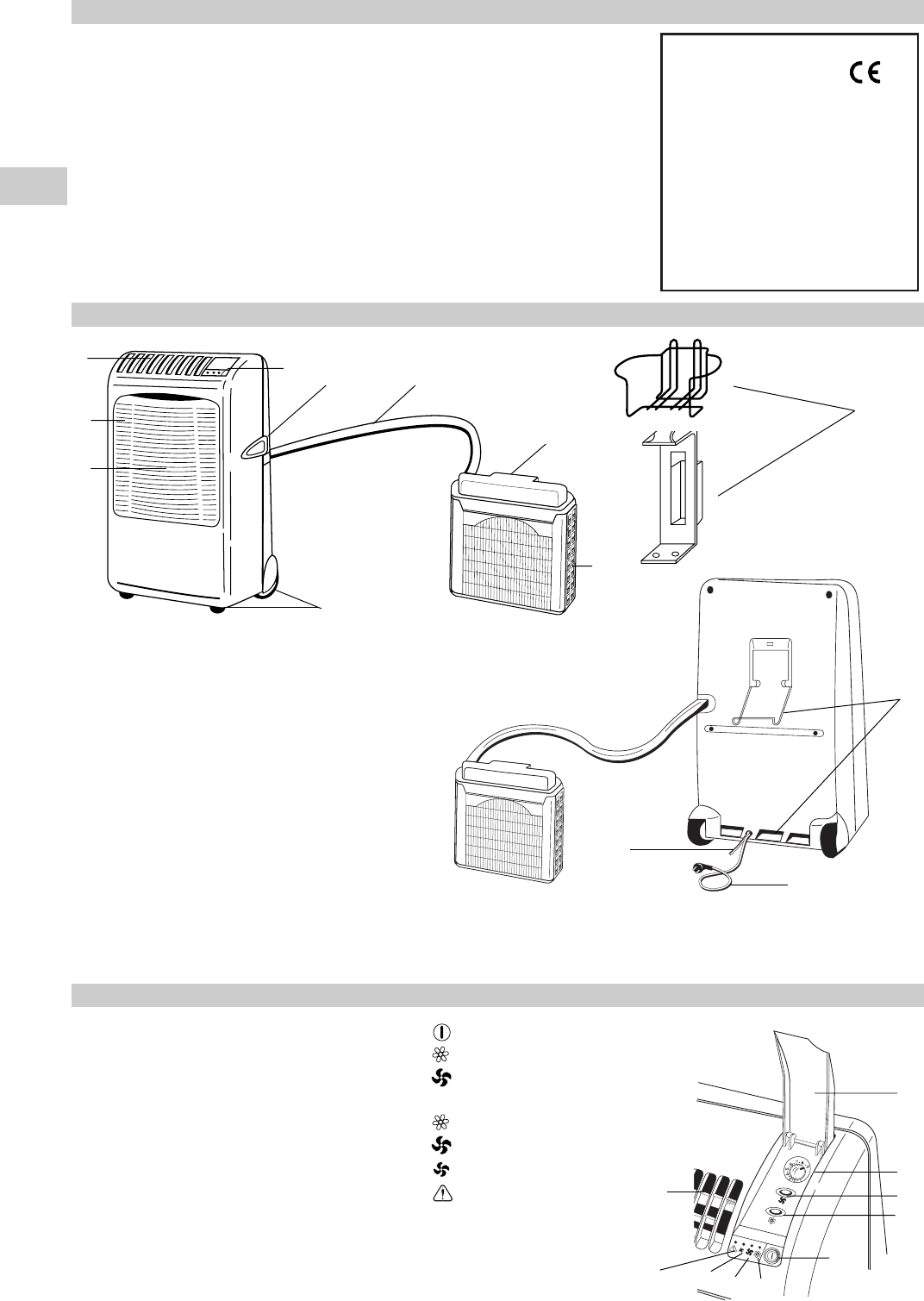
1. Cleaning of the Air Filter
The air filter must be cheked at least once every two weeks
operation. Operation with a dirty filter always causes a lower
efficency of the air conditioner and severe product damage.
The filter is located at the back of the intake grille in the front
of the air-conditioner and shall be removed from the upper
side of the unit. Use a vacuum cleaner to remove light dust. If
there is sticky dust on the filter, wash it with lukewarm soapy
water, then rinse in clean, cold water and dry it before reinstal-
lation.
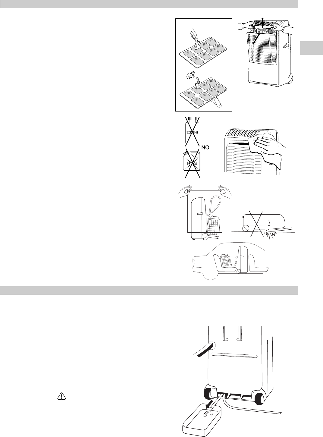
2. Cleaning of Casing and Grille.
To clean the air conditioner, wipe it with a clean soft cloth,
lightly moisted. In case it is stained, moisten the cloth with
soapy water. Never use solvents or harsh chemicals, nor very
hot water. Do not pour water over the air conditioner to clean
it: this will damage the internal components and cause an
electric shock hazard.
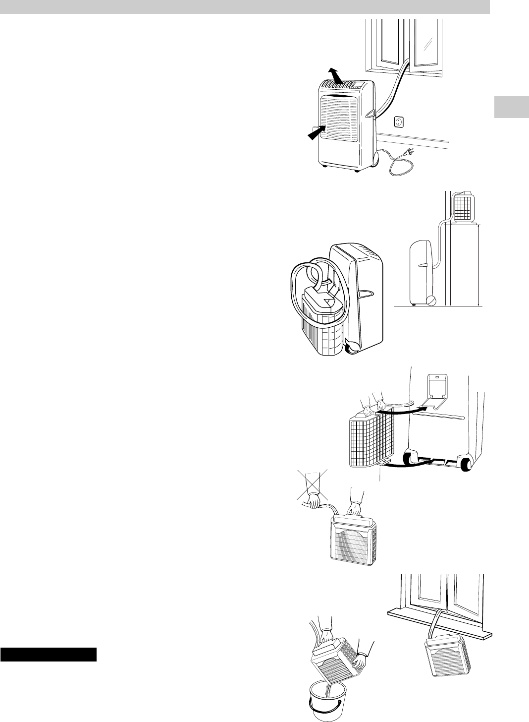
3. Storage.
If you are not going to make use of the air conditioner for a
long period, before storing it away clean the air filter and eva-
cuate the condensate from the indoor unit through the rear
drain pipe and from the outdoor unit tilting it. Do not discon-
nect the flexible tube, unless you are obliged to do it: in that
case protect the open halves of the couplings with the plugs
supplied as accessories, that must be tightened with a span-
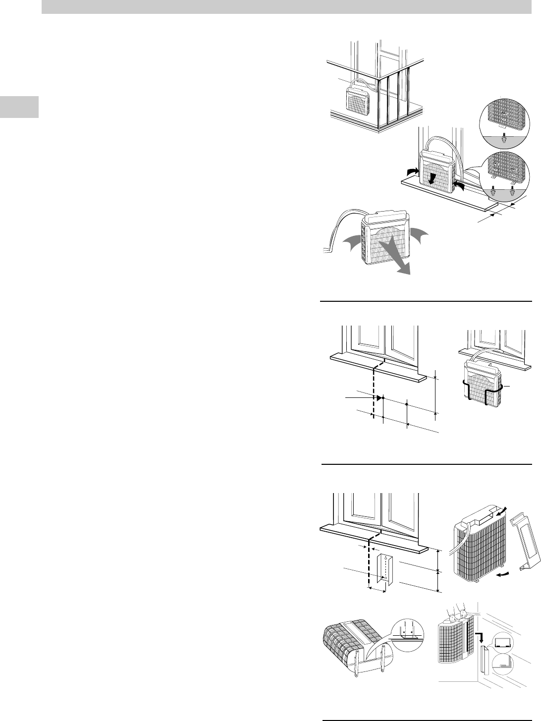
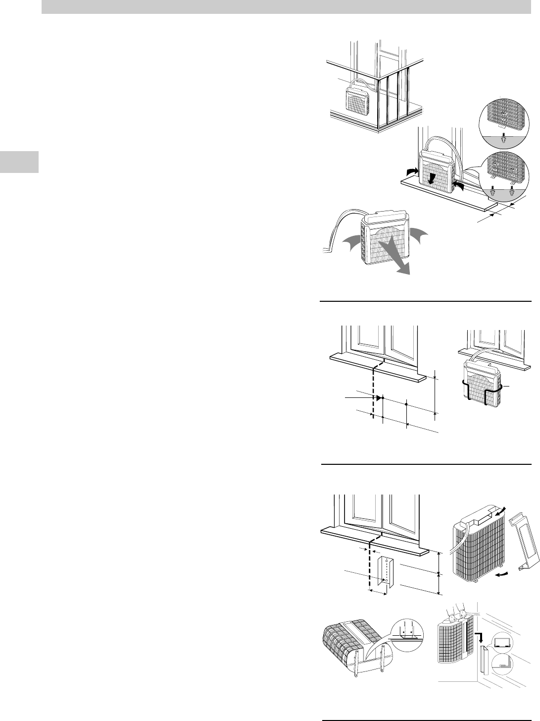
ner. Always store the unit in the vertical position hanging the
outdoor unit by the handie to the rear of the indoor unit. Do
not put heavy objects on top of the unit and protect it with a
cloth or a plastic bag.
4. Transport.
Preferably keep the air conditioner in the vertical position
during transportation. If this is not possible, then lay it on one
side; when at destination put the air conditioner back in the
vertical position and wait at least 10 minutes before using it for
cooling.
5. For your safety care check periodically the conditions of
the electric supply cable; the electrical connection of the
unit is X type with cable prepared in a special way; in case
you should notice any damage due to usage, call the neare-
st After Sale Service to get the cable replaced.
If your air conditioner doesn’t work properly, first check the following
points before requesting service:
the plug is properly inserted into the power socket;
the circuit breaker is in the ON position and fuses have not blown;
the air filter is not clogged;
the flexible tube is correctly positioned without any sharp bends nor plies;
the thermostat knob is in the proper position for the suitable tempe-
rature (twisting it clockwise verify the compressor re-start, after the
delayed time);
the room temperature is above 15 °C;
you have correctly carried-out the instructions contained in this
manual;
The lighting-up of lamp , together with the stop of the air conditio-
ner indicate that the condensate pump is not working or that the con-
densate drain pipe in the flexible connection pipe is obstructed. In this
case contact the After Sale Service.
In case of emergency the air conditioner can work by draining
the condensate from the back little pipe into a rather short con-
tainer; extract the little pipe and remove the cap. (See picture)
7
EG
NO!
FILTER CLEANING
DICHIARAZIONE DI CONFORMITÀ
Questo prodotto è marcato in
quanto conforme alle Direttive:
Bassa Tensione n. 73/23 CEE e
93/68 CEE.
Compatibilità Elettromagnetica n.
89/336 CEE, 92/31 CEE e 93/68
CEE.
Questa dichiarazione sarà nulla nel
caso di impiego diverso da quello
dichiarato dal Fabbricante e/o di
mancata osservanza, anche solo
parziale, delle istruzioni d'installazione
e/o d'uso.
Condizioni limite di funzionamento:
2
IL PRODOTTO
PANNELLO COMANDO E CONTROLLO
01. Pannello comando e controllo
02. Deflettore mandata aria
, 3. Maniglia trasporto (su entrambi i lati)
04. Griglia aspirazione aria
05. Ruote trasporto
06. Unità esterna
07. Tubo flessibile
8. Maniglia (appensione e trasporto)
09. Filtro aria
10. Cavo eletttrico con spina
11. Aggancio per unità esterna
12. Tubetto servizio scarico condensa
13. Contenitore o supporto unità esterna
I
INDICE
IL PRODOTTO ....................................................................................................2
PANNELLO COMANDO E CONTROLLO .......................................................... 2
PRIMA DI USARE IL CLIMATIZZATORE ...........................................................3
INSTALLAZIONE DEL CLIMATIZZATORE ........................................................ 4
MODALITÁ D'USO
Raffreddamento .......................................................................................5
Solo ventilazione ......................................................................................5
REGOLAZIONE FLUSSO D'ARIA ...................................................................... 5
ACCESSORI (FORNITI SU RICHIESTA) ........................................................... 6
Filtro aria pulita .........................................................................................6
Kit contenitore o guida supporto unità esterna supplementari .................6
MANUTENZIONE E CURA .................................................................................7
CONSIGLI UTILI ..................................................................................................7
Temperatura interna: Temperatura esterna:
MIN: 15° C B.S. / 12° C B.U. MIN: 15° C B.S.
MAX: 32° C B.S. / 23° C B.U. MAX: 46° C B.S.
12
5
4
2
9
6
3
1
7
8
11
13
10
CONTENITORE
SUPPORTO
1. Pulsante marcia/arresto
2. Pulsante raffreddamento
3. Pulsante alta / bassa velocità ventilatore
4. Manopola termostato elettronico
5. Spia raffreddamento
6. Spia alta velocità ventilatore
7. Spia bassa velocità ventilatore
8. SPIA ALLARME LIVELLO ACQUA (ROSSO)
Si accende per malfunzionamento del sistema di evacuazione condensa.
9. Sportello comandi
10. Deflettore mandata aria in posizione per mandata verticale
10
8
7
6
1
5
2
3
4
9
3
PRIMA DI USARE IL CLIMATIZZATORE
Verificare che la tensione monofase di alimentazione nel luogo di
utilizzo sia di 220V-240V~ 50Hz.
Assicuratevi che l'impianto elettrico sia in grado di erogare la cor-
rente di esercizio necessaria per il climatizzatore oltre a quella
assorbita normalmente da altre utenze (elettrodomestici, illumina-
zione). Vedere gli assorbimenti massimi sulla targhetta dati posta
sul climatizzatore.
Si raccomanda l'installazione di un interruttore bipolare, con fusibi-
le di protezione da 10 A del tipo ritardato, a monte della presa d'ali-
mentazione.
L'allacciamento alla rete elettrica del climatizzatore deve essere
eseguito in conformità alle norme d'installazione vigenti.
Assicuratevi che interruttori automatici e valvole di protezione del-
l'impianto siano in grado di sopportare una corrente di spunto di 35
A, (normalmente per un tempo inferiore a 1 secondo).
Evitare di installare il climatizzatore in locali dove potrebbe essere
investito da spruzzi d'acqua (es. lavanderie).
Accertatevi che il pulsante marcia - arresto sul pannello di coman-
do del climatizzatore sia nella posizione OFF.
La presa dell'impianto deve essere sempre provvista di messa a
terra efficiente.
Non usare mai la spina come mezzo per arrestare o avviare il cli-
matizzatore: usare sempre il pulsante marcia/arresto sul pannello
di comando dell'unità.
PRECAUZIONE!
Non inserite oggetti nel condizionatore. É molto pericoloso perché
il ventilatore gira ad alta velocità.
ATTENZIONE!
Il climatizzatore è dotato di un sistema di protezione del compresso-
re dai sovraccarichi che non consente la partenza del compressore
se non sono trascorsi almeno 3 minuti da un precedente arresto.
Evitare quindi spostamenti veloci della manopola termostato nei due
sensi quando il compressore è in funzione.
Assicurare la libera circolazione dell'aria all'unità interna. Non
ostruire con tendaggi o simili la griglia di aspirazione e quella di
mandata. La parte superiore deve essere libera da qualsiasi osta-
colo, non depositare oggetti sul climatizzatore.
Il costruttore non si assume responsabilità alcuna nel caso in cui le
norme di sicurezza e antinfortunistiche non vengano rispettate.
AVVERTENZE IMPORTANTI
1.Per rendere agevoli gli spostamenti del climatizzatore, appendete
l'unità esterna al gancio posto sul retro dell'unità interna, avendo
cura di non torcere il tubo flessibile, né fargli compiere curve con
raggio molto stretto.
2.Per spostare l'unità esterna, afferratela sempre per la maniglia, mai
per il tubo flessibile.
3.Non lasciate mai penzolare l'unità esterna dalla finestra, appesa al
tubo flessibile.
4.Quando ritirate l'unità esterna dopo il funzionamento, scaricate l'e-
ventuale condensa residua inclinando l'unità.
I
Prima di eseguire una qualsiasi operazione di spostamento o pulizia,
assicuratevi che la spina sia disinserita dalla presa di corrente.
Alcuni bordi e le alette della batteria condensante possono causare
danni se maneggiati in modo improprio: usate le necessarie cautele
quando pulite queste parti.
AVVERTIMENTO
MASSIMO DISLIVELLO
1000
UNITA’ INTERNA
NO!
NO!
4
POSIZIONAMENTO UNITÀ ESTERNA
L'unità esterna deve sempre essere mantenuta in posizione
verticale e ben livellata. Assicurarsi che non vi siano ostacoli
alla libera circolazione dell'aria. Un piedino sporgente sul
retro dell'unità garantisce la minima distanza dalla parete (3
cm).
Garantire una distanza minima da eventuali pareti di cm. 15
sui lati e cm. 80 sul fronte dell'unità.
INSTALLAZIONE TIPO A
Se disponete di un balcone, oppure di una finestra con
davanzale abbastanza profondo (min. 25 cm) potete appog-
giare l'unità esterna liberamente. Per maggiore sicurezza
consigliamo di fissare il piedino posteriore dell'unità al
davanzale con un tassello ad espansione M6 x 20.
Il tubo flessibile potrà passare facilmente tra i battenti acco-
stati della finestra o porta-balcone, bloccati in posizione di
minima apertura.
INSTALLAZIONE TIPO B (CON CONTENITORE)
1. Fissare il contenitore al muro sotto il davanzale della
finestra.
2. Inserire l’unità esterna nel contenitore e controllare che
sia a livello.
INSTALLAZIONE TIPO C (CON SUPPORTO)
1. Fissare la guida supporto al muro sotto il davanzale della
finestra.
2. Inserire il supporto nella maniglia dell’unità esterna e
capovolgere quest’ultima come da figura.
3. Posizionare il supporto e fissarlo al bordo dell’unità
esterna con le viti.
4. Inserire il supporto fissato all’unità esterna nella
guida fissata al muro. Verificare che sia a livello.
I
2 fori ø 10
SUPPORTO
CONTENITORE
2 fori ø 10
guida
supporto
200
210
1
0
0
m
in
.
2
0
0
140
50
Il climatizzatore è composto da due unità collegate tra di loro da un
tubo flessibile. L'unità interna, mobile su ruote, va collocata nel
locale da condizionare, in prossimità di una finestra, porta-balcone
o parete esterna. L'unità esterna, che assicura lo smaltimento del
calore e della condensa, va collocata all'esterno, sul davanzale
della finestra, sul balcone o appesa al muro.
Min. 25 cm.
M6 x 20
M6 x 20
INSTALLAZIONE DEL CLIMATIZZATORE
TIPO A
TIPO B
TIPO C
4
POSITION DER AUßENEINHEIT
Die Außeneinheit muß immer stehen und gut nivelliert sein.
Vergewissern Sie sich, daß kein Gegenstand den
Luftumlauf hindert. Ein überstehender kleiner Fuß auf der
Rückseite der Einheit sichert einen Kleinstabstand von der
Wand (3 cm.). Sie sollten einen Mindestabstand von cm. 15
(seitlich) und cm. 80 (stirnseitig) zwischen der Einheit und
eventuellen Wänden schaffen.
AUFSTELLUNG TYP A
Wenn es einen Balkon oder ein tiefes Fensterbrett vom
min.25 cm. gibt, können Sie die Außeneinheit dahin stellen.
Es wird empfohlen, den kleinen Fuß der Einheit dem
Fensterbrett durch einen Spreizdübel M6x20 aufzuschrau-
ben. Den Schlauch zwischen den Flügeln der Tür durch-
stecken. Die Flügel sollen angelehnt bleiben.
AUFSTELLUNG TYP B (MIT STÜTZKORB)
1. Den Stützkorb an der Wand unter dem Fensterbrett befe-
stigen.
2. Die Einheit in den Korb stellen und vergewissern Sie sich,
daß sie nicht geneigt ist.
AUFSTELLUNG TYP C (MIT HALTER)
1. Den Halterungsführung an der Wand unter dem
Fensterbrett befestigen.
2. Den Halter in den Außeneinheitsgriff einsetzen und die
Einheit umwenden (sieh das Bild).
3. Den Halter auf den Rand der Einheit mit den Schrauben
befestigen.
4. Den auf der Einheit befestigte Halter an die Wand einset-
zen. Die Einheit muß nicht geneigt sein.
D
2 löcher ø 10
HALTER
STÜTZKORB
2 löcher ø 10
Halterungsfü
hrung
200
210
1
0
0
m
in
.
2
0
0
140
50
Das Klimagerät besteht aus zwei Einheiten, die untereinander
durch einen Schlauch verbunden sind. Die auf 2 Räder fahrbare
Inneneinheit in den zu klimatisierenden Raum, neben ein Fenster,
eine Balkonstür oder eine Außenwand stellen. Die Außeneinheit,
die die Wärme- und Kondenswasser-Beseitigung erlaubt, hinaus
auf das Fensterbrett, auf den Balkon stellen, oder sie an die Wand
hängen.
Min. 25 cm.
M6 x 20
M6 x 20
KLIMAGERÄTEAUFSTELLUNG
TYP A
TYP B
TYP C
22


Need help? Post your question in this forum.

Forumrules


Report abuse

Libble takes abuse of its services very seriously. We're committed to dealing with such abuse according to the laws in your country of residence. When you submit a report, we'll investigate it and take the appropriate action. We'll get back to you only if we require additional details or have more information to share.

Product:

For example, Anti-Semitic content, racist content, or material that could result in a violent physical act.

For example, a credit card number, a personal identification number, or an unlisted home address. Note that email addresses and full names are not considered private information.

Forumrules

To achieve meaningful questions, we apply the following rules:

Register

Register getting emails for Argo OSCAR TWIN 14 - AMR214CTA at:


You will receive an email to register for one or both of the options.


Get your user manual by e-mail

Enter your email address to receive the manual of Argo OSCAR TWIN 14 - AMR214CTA in the language / languages: English, German, French, Italian, Portuguese, Spanish as an attachment in your email.

The manual is 1,68 mb in size.


You will receive the manual in your email within minutes. If you have not received an email, then probably have entered the wrong email address or your mailbox is too full. In addition, it may be that your ISP may have a maximum size for emails to receive.

The manual is sent by email. Check your email

If you have not received an email with the manual within fifteen minutes, it may be that you have a entered a wrong email address or that your ISP has set a maximum size to receive email that is smaller than the size of the manual.

The email address you have provided is not correct.

Please check the email address and correct it.

Your question is posted on this page

Would you like to receive an email when new answers and questions are posted? Please enter your email address.


Info