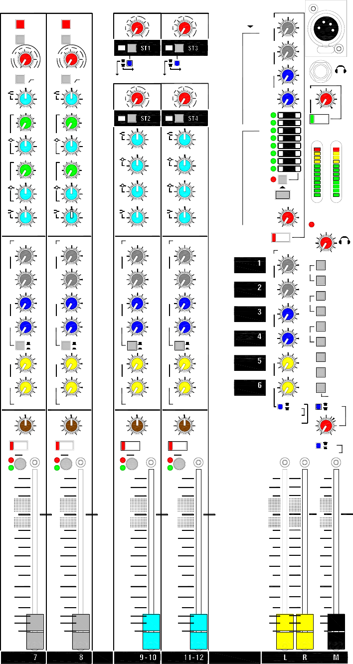
is provided. Select the source to listen to using the monitor switch
bank. With no switch pressed the post-fade LR mix is monitored.
Press M to listen to the post-fade M source. Pressing any switch
higher up the bank overrides the previous selection. Pressing ST1
(ST5) listens to the wet effects only return signal if the internal effects
processor is active. Pressing Aux pairs 1-2, 3-4, 5-6 together listens to
the two selected auxes as a stereo pair. The two console meters
display the selected monitor source signal level.
Pressing channel PFL switches automatically overrides the current
monitor selection with the pre-fade signal from that channel or
selection of channels. The red PFL active indicator lights and the
console meters display the channel signal.
We recommend you use closed ear headphones in the range 30 to
600 ohms designed for live sound monitoring. Headphones around
100 ohms impedance are a popular choice.
WARNING: To avoid damage to your hearing do not operate
any close-to-ear monitoring such as headphones for long periods
at high volume. Continued exposure to high volume sound can
cause frequency selective or wide range hearing loss.
ST2 (ST6) RETURN This is a simple stereo return channel that
routes to the main LR mix. The typical application is to plug in a CD or
similar playback device for walk-in or background music. It can also be
used as an additional effects return. Adjust the volume using the LEV
control. Route the signal to LR by pressing the TO LR switch. The
green LED lights to warn that the source is routed to LR.
You can use the ST2 (ST6) input to monitor your 2-track recording.
Press the ST2 (ST6) monitor source select switch. Use the AB output
to feed your recorder. If you are monitoring while mixing live, make
sure you do not accidentally press the TO LR switch and route your
recording to the house speakers.
PHONES
TO LR
OO
R
PHONES
10
AUX 1
AUX 2
AUX 4
AUX 5
AUX 3
0
-6
-9
-3
L
PFL
0
1-2
3-4
5-6
+16
+9
+6
+3
-12
-16
-20
-30
ST5
ST6
M
0
ALL UP = LR
MONITOR
ALT LR OUT
AB
AUX 6
+10OO
/ FX
0
WZ
3
16:2 and 12:2 User Guide 23
Gain Structure
How the levels between the different signal stages are set up is referred to as the
gain structure
. For best performance it is important that the connected source
signals are matched to the ‘normal operating level’ of the console. Similarly the
levels of the connected amplifiers and destination equipment should be correctly
matched to the console outputs. If set too high then the signal peaks will be
clipped resulting in distortion, and if set too low then the signal-to-noise
performance will be degraded resulting in excessive background hiss and noise.
Using the Meters The MixWizard provides metering of inputs and outputs.
For best results operate the console with the main meters averaging around ‘0’
allowing the loudest moments to reach ‘+6’. Reduce the channel gain settings if
the red peak indicators start to flash. Note that the peak indicators light 5dB
before actual clipping to warn that you are nearing distortion and should reduce
gain. The LED bar meters have a ‘quasi-peak’ response with fast attack and slow
release so that fast musical transients are accurately displayed.
Matching a Source to the Console Start by turning down the channel
fader and send levels to prevent unexpected loud volumes reaching the main
speakers and monitors. Using PFL, adjust the GAIN control for an average ‘0’
reading on the console meters. These automatically switch to show the channel
pre-fade signal when PFL is pressed. Listen to the signal using headphones or
local AB monitor. Once the channel gain is correctly set you can raise the levels
to bring the channel into the mix. Note that you may need to adjust the gain if you
make significant changes to the EQ. Make sure that any equipment inserted into
the channel is set to operate around 0dBu line level. First set the gain with
inserted signal processors such as compressors switched to bypass.
Matching the Console to Destination Equipment The console
produces a standard XLR output level of +4dBu for a meter reading of ‘0’. It can
produce a maximum of +26dBu which is more than is usually required and
therefore gives you plenty of headroom. If you are connecting to a sensitive
power amplifier it is advisable to turn down its input trim control if the normal
console level is too high. Simply turning down the console output faders
degrades the output stage noise performance and reduces the resolution of the
fader movement. The output faders are best operated around ‘-10’ to ‘0’ for
loudest average volume required. This allows additional headroom if you need it.
Terminology The normal operating level is the optimum signal level for best
console performance, indicated by ‘0’ meter readings and resulting in the +4dBu
XLR output level. The channels operate at 0dBu and the mix stages at –2dBu for
extended headroom. Headroom
is the extra level available above normal to allow
for loud peaks before the signal becomes clipped
resulting in audible distortion.
The signal-to-noise ratio
(SNR) is the difference measured in dB between normal
level and residual noise floor
(hiss) produced by the console electronics. The
dynamic range
is the sum of headroom and SNR representing the maximum
signal range possible from quietest to loudest.
Final word… A little care with setting gain structure throughout the signal
chain will give you the best performance and most manageable control of the mix.
24WZ
3
16:2 and 12:2 User Guide
Specifications
Performance
Maximum output level XLR +26dBu into 600 ohms max load
Jack +21dBu into 2k ohm max load
Internal headroom Channels +21dB
Mix +23dB
Meters 3 colour LED, quasi peak response
Sensitivity 0VU = +4dBu at XLR output
Master meters 12 segment -30 to +16dB
Channel meters 2 segment -12, +16dB (5dB before clip)
Frequency response 20Hz to 50kHz +/-0.5dB
THD+n at +10dBu 1kHz Channel to mix out < 0.004%
Crosstalk at 1kHz Fader shutoff >90dB
Channel mute >100dB
Inter channel >90dB
Noise, rms 22Hz to 22kHz Mic EIN -128dB
Residual output noise < -95dBu (-99dB S/N)
LR unity fader mix noise < -83dBu (-87dB S/N)
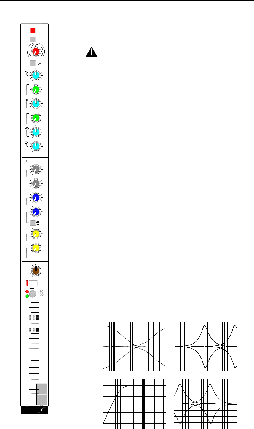
Channel HPF 12dB/octave below 80Hz
Mono EQ HF Shelving, +/-15dB, 12kHz
HM Peak/dip, +/-15dB, 500Hz to 15kHz, Q=1.8
LM Peak/dip, +/-15dB, 35Hz to 1kHz, Q=1.8
LF Shelving, +/-15dB, 80Hz
Stereo EQ HF Shelving, +/-15dB, 12kHz
HM Peak/dip, +/-15dB, 2.5kHz, Q=1.8
LM Peak/dip, +/-15dB, 250Hz, Q=1.8
LF Shelving, +/-15dB, 80Hz
Power supply Internal 100-240V, 50/60Hz auto sensing, IEC input
External Input for optional MPS12 backup supply
Power consumption 35W max
Mains fuse T630mA L 20mm
Mechanical
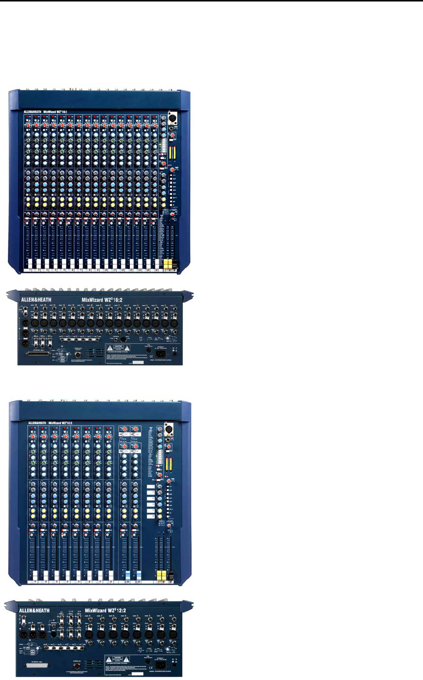
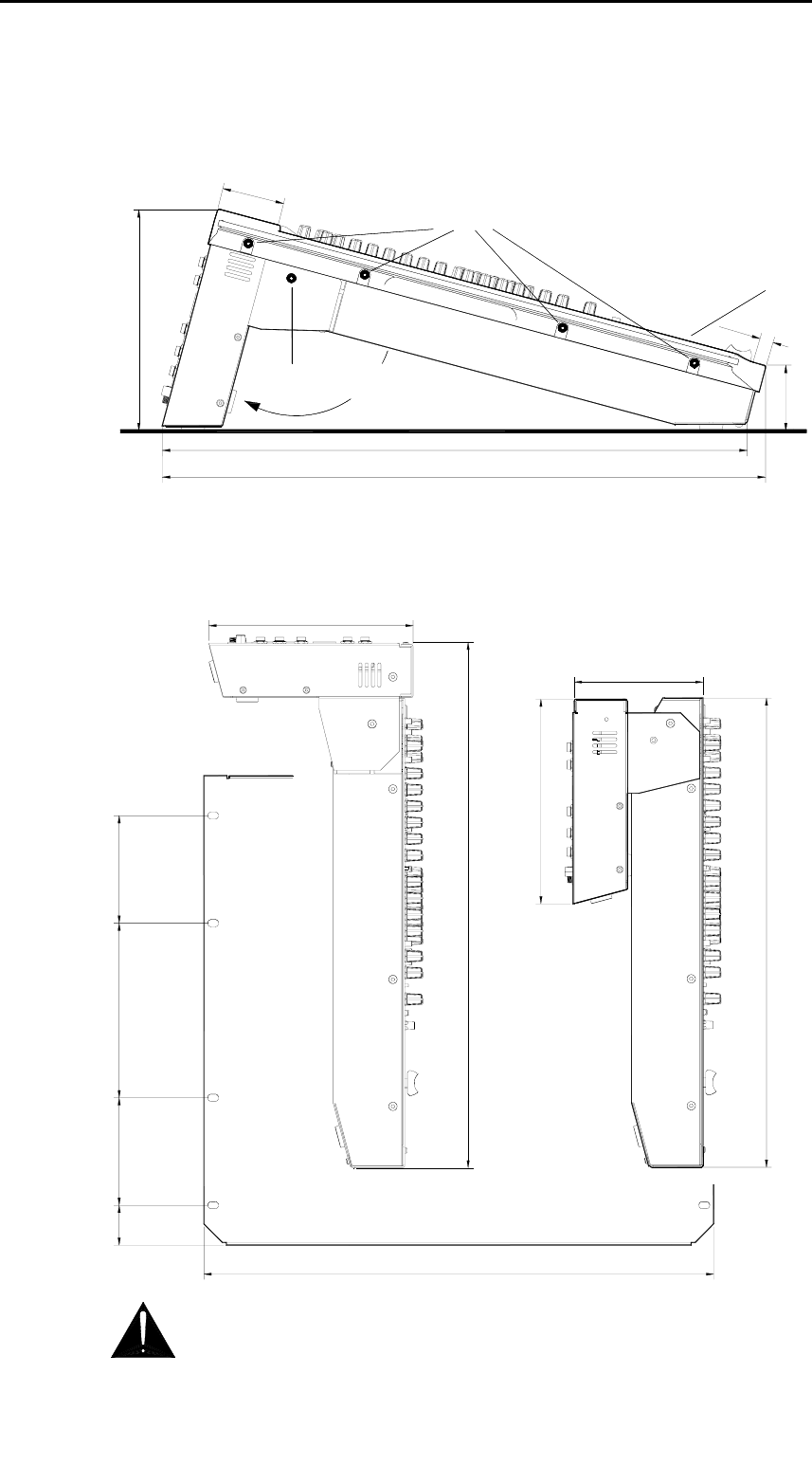
Free standing dimensions W 507 (20”) x D 530 (20.9”) x H 194 (7.7”)
Rack mounted W 483 (19”) x D 122 (4.8”) x H 444 (17.5”) 10U
Underside connectors
Rack mounted W 483 (19”) x D 193 (7.6”) x H 497 (19.6”) 11.2U
Rear connectors
Weight 10kg (22lbs)
WZ
3
16:2 and 12:2 User Guide 25
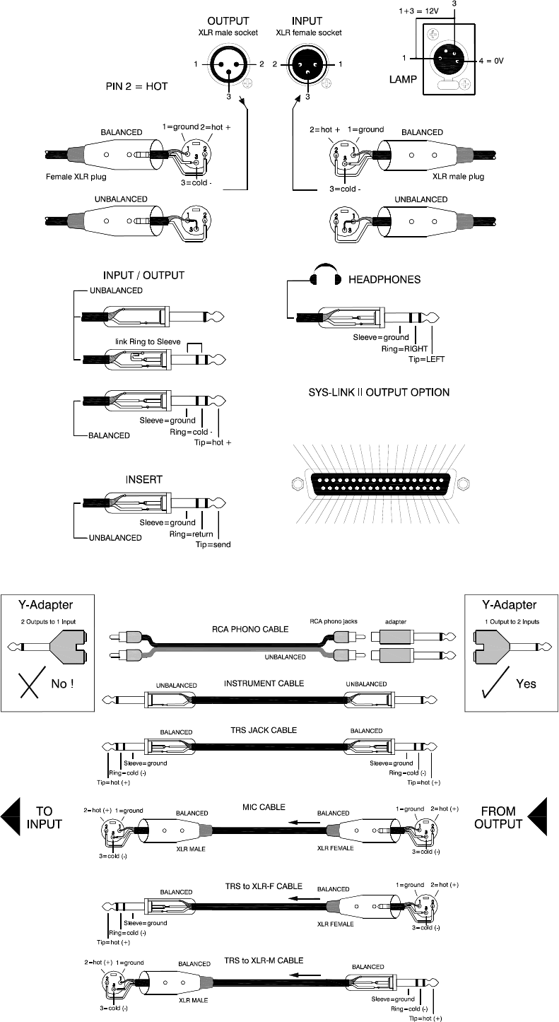
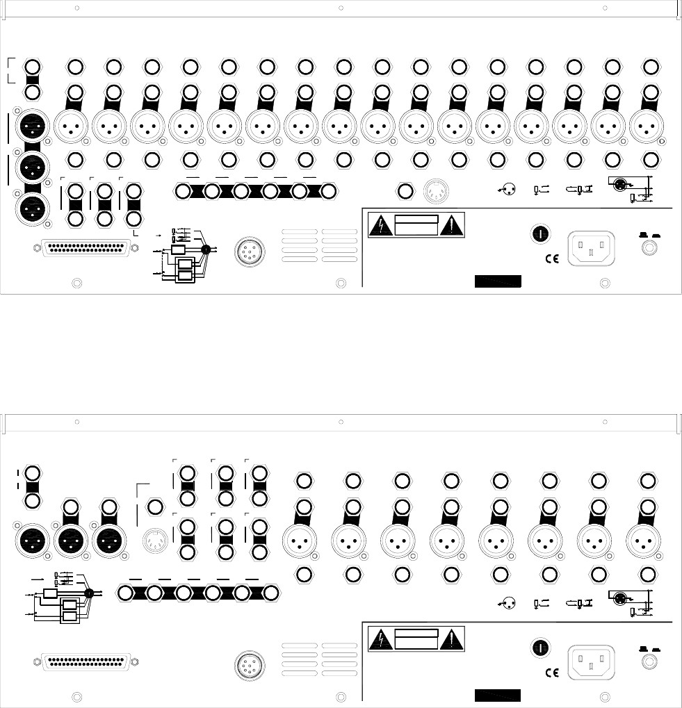
Connections
Mono channel XLR balanced pin 2 hot Sensitivity -60 to +10dBu
TRS balanced, tip hot Sensitivity -40 to +10dBu
Pad out (MIC) 2k ohm
Pad in (MIC or LINE) >10k ohm, -20dB
Max input level +30dBu
XLR phantom power +48V, on/off
Stereo channel ST1,3 TRS unbalanced >10k ohm, -16 to +20dBu
ST2,4 TRS balanced >10k ohm, -16 to +20dBu
Stereo returns ST1(5) TRS balanced >10k ohm, -6 to +20dBu
ST2(6) TRS unbalanced >2k ohm, -2 to +20dBu
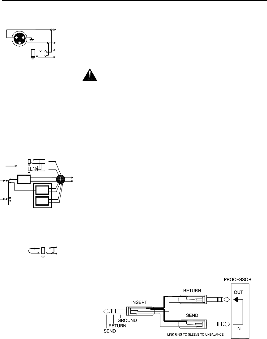
Inserts Channel TRS, tip send, ring return, 0dBu
Output TRS, tip send, ring return, -2dBu
L, R, M outputs XLR balanced pin 2 hot <75 ohm, +4dBu, +26dBu max
Aux 1-6 output TRS impedance balanced <75 ohm, -2dBu, +21dBu max
Electronic balance option <75 ohm, +4dBu, +26dBu max
Direct out TRS impedance balanced <75 ohm, 0dBu, +21dBu max
AB out TRS impedance balanced <75 ohm, -2dBu, +21dBu max
Headphones TRS, tip L, ring R, 30 to 600 ohm headphones recommended
Lamp 4-pin XLR max 12V 5W lamp
MixWizard 3 Series Part Numbers
WZ
3
12:2 8 mic/line, 2 dual stereo, LR console W31202/v
WZ
3
16:2 16 mic/line LR console W31602/v
WZ
3
14:4:2 10 mic/line, 2 dual stereo, 4 group console W31442/v
WZ
3
12:2 and WZ
3
16:2 Sys-Link II output option kit W312/16-SLV2
WZ
3
14:4:2 Sys-Link II input/output option kit W31442-SLV2
SSM2142P balanced output driver option IC AE0302
DRV134 balanced output driver option IC (alternative to above) AE5725
Allen & Heath MPS12 backup power supply option MPS12/v
Allen & Heath 18” gooseneck LED lamp LEDLAMP
26WZ
3
16:2 and 12:2 User Guide
A OUT
TIP= +
TIP= +
B OUT
JP1
MS
SUM
+
MONO/STEREO AUX SOURCE
C
D
B
A
LKJI
HGJUMPEREF
P = PRE-FADE
S = SWITCHED
A = POST-FADE
+
-
GAIN
-20dB
LINE (PAD)
HPF
48V
MIC/LINE INPUTS
ST2 TO LR
SIG
PK
MUTE
A
3
PS
4
5
AS
PRE
6
S
AUX1
AUX2
STEREO 1-2
MONITOR SELECT
AUX3
PFL MIX
PFL DC
AUX 1-6
PAN
AUX1-6 TO MONITOR
AUX MIX
MASTER
PFL
LEFT
RIGHT
MONITOR METERS
MONITOR
PFL
ACTIVE
LEV
HEADPHONES
L
R
+4dBu BAL OPTION
IMPEDANCE BALANCED
-2dBu
TIP= +
AUX OUT
R
L
MODE
AUX 6
AUX 5
9-16
SINGLE
EFFECT
DUAL
1-16
1-8
EFFECT
EFFECT
MIDI PARAMETER EDIT
+
FOOTSWITCH
AUX5,6 TO FX, AUX6 TO C
EFFECTS
FROM AUX5,6
BAL
+4dBu
L-R
MONITOR
LEV
A-B
-2dBu IMPEDANCE BALANCED
A-B
AUX SENDS 1-6
IMPEDANCE BALANCED
DIRECT OUT
WZ3 16:2
TIP= +
RING= -
0dBu
POST-EQ
PRE-INSERT, PRE-EQ
POST-FADE
PRE-FADE
P
1
AUX
2
S
HF
LM
4 BAND EQUALISER
HM
LF
PHANTOM POWER
PFL
FADER
ST2 IN
ST1 IN (EXT EFFECTS IN)
TO MONITOR
LR
+
BALANCED 0dBu
R
L/M
-
+
-
+
SUM
AUX1
AUX2
MUTE
TO MONITOR
LR
R MIX
FROM AUX6
L MIX
PRE-FADE
POST-FADE
ST1 (EFFECTS)
ST2
ALL UP= L-R
M
AUX4
AUX5
AUX6
STEREO 5-6
MONO SUM
AUX6
+
SUM
M FADER
L FADER
-2dBu
-2dBu
R FADER
+4dBu
M OUT
2 = +
BAL
+4dBu
LEFT OUT
RIGHT OUT
2 = +
2 = +
L-R
BAL
M
STEREO 3-4
INSERT
INSERT
UNBALANCED -2dBu
STEREO RETURN 2
STEREO RETURN 1
R
L/M
SYS-LINK CONNECTION
SL
SL
SL
SL
SL
SL
INSERT
0dBu
LINE
BALANCED
TIP= +
MIC
2= +
RING= RETURN
TIP= SEND
AUX3
AUX4
WZ
3
16:2
WZ
3
16:2 and 12:2 User Guide 27
B OUT
TIP= +
TIP= +
A OUT
A-B
-2dBu IMPEDANCE BALANCED
A
B
C
D
FEJUMPERGH
IJKL
CN4
BADCFEHGJILKJUMPER OPTIONS
P = PRE-FADE
S = SWITCHED
A = POST-FADE
MSMS
CN5
PRE-FADEPOST-FADE
R
PRE
LRL
SM
MONO/STEREO AUX SOURCE
JP1
A = POST-FADE
S = SWITCHED
P = PRE-FADE
0dBu
INSERT
+
AUX4
AUX3
FROM AUX5,6
EFFECTS
AUX5,6 TO FX, AUX6 TO C
FOOTSWITCH
+
MIDI PARAMETER EDIT
EFFECT
EFFECT
1-8
1-16
DUAL
EFFECT
SINGLE
9-16
AUX 5
AUX 6
MODE
RIGHT
LEFT
PFL
AUX MIX
PAN
AUX 1-6
S
6
PRE
SA
5
4
SP
3
A
MUTE
+
SUM
HF
LM
LF
+
HM
ON
GAIN
ON
GAIN
LR
CH
4 BAND EQUALISER
FADER
+
-
L/M
INPUT ST2(4)
+
-
R
DUAL STEREO INPUTS
SIG
PK
INPUT ST1(3)
L/M
R
++
PRE
MONO/STEREO AUX
6
SAA
4
S
5
S
3
PSPPS
2
S
AUX
P
1
PAN
MUTE
PFL
PK
SIG
ST2 TO LR
MIC/LINE INPUTS
48V
HPF
LINE (PAD)
-20dB
GAIN
-
+
TIP= SEND
RING= RETURN
2= +
MIC
TIP= +BALANCED
LINE
L
R
SL
SL
SL
SL
SL
SL
SYS-LINK CONNECTION
AUX OUT
TIP= +
-2dBu
IMPEDANCE BALANCED
+4dBu BAL OPTION
R
L
HEADPHONES
LEV
ACTIVE
PFL
MONITOR
MONITOR METERS
MASTER
AUX1-6 TO MONITOR
PFL DC
PFL MIX
AUX3
MONITOR SELECT
STEREO 1-2
AUX2
AUX1
AUX SENDS 1-6
A-B
LEV
MONITOR
L-R
+4dBu
BAL
BAL
L-R
2 = +
2 = +
RIGHT OUT
LEFT OUT
+4dBu
BAL
2 = +
M OUT
+4dBu
R FADER
-2dBu
-2dBu
L FADER
M FADER
SUM
+
AUX6
MONO SUM
STEREO 5-6
AUX6
AUX5
AUX4
M
ALL UP= L-R
ST6
ST5 (EFFECTS)
POST-FADE
L MIX
FROM AUX6
R MIX
INSERT
INSERT
STEREO 3-4
STEREO RETURN
M
FADER
PFL
PHANTOM POWER
LF
HM
4 BAND EQUALISER
LM
HF
S
2
AUX
1
P
PRE-FADE
POST-FADE
PRE-INSERT, PRE-EQ
POST-EQ
0dBu
RING= -
TIP= +
WZ3 12:2
DIRECT OUT
IMPEDANCE BALANCED
LR
TO MONITOR
MUTE
SUM
AUX2
AUX1
SUM
+
-
+
-
L/M
R
BALANCED 0dBu
+
LR
TO MONITOR
ST6 IN (EXT EFFECTS IN)
ST6 IN
L/M
R
STEREO RETURN
UNBALANCED -2dBu
WZ
3
12:2
28WZ
3
16:2 and 12:2 User Guide
FX Parameters:This table shows the factory default preset settings. These may be edited via MIDI using the Allen & Heath MixWizard FX Editor software running on a PC.
FX Types Available:This table shows the effects types available. You may change the factory defaults to other types shown here using the FX Editor software.
Note that effects type W can only be used in single mode. Effects type H can be used in both single and dual mode.
Libble takes abuse of its services very seriously. We're committed to dealing with such abuse according to the laws in your country of residence. When you submit a report, we'll investigate it and take the appropriate action. We'll get back to you only if we require additional details or have more information to share.
Product:
Forumrules
To achieve meaningful questions, we apply the following rules:
First, read the manual;
Check if your question has been asked previously;
Try to ask your question as clearly as possible;
Did you already try to solve the problem? Please mention this;
Is your problem solved by a visitor then let him/her know in this forum;
To give a response to a question or answer, do not use this form but click on the button 'reply to this question';
Your question will be posted here and emailed to our subscribers. Therefore, avoid filling in personal details.
Register
Register getting emails for Allen-Heath MixWizard WZ3-16 at:
new questions and answers
new manuals
You will receive an email to register for one or both of the options.
Get your user manual by e-mail
Enter your email address to receive the manual of Allen-Heath MixWizard WZ3-16 in the language / languages: English as an attachment in your email.
The manual is 4,55 mb in size.
You will receive the manual in your email within minutes. If you have not received an email, then probably have entered the wrong email address or your mailbox is too full. In addition, it may be that your ISP may have a maximum size for emails to receive.
If you have not received an email with the manual within fifteen minutes, it may be that you have a entered a wrong email address or that your ISP has set a maximum size to receive email that is smaller than the size of the manual.
The email address you have provided is not correct.
Please check the email address and correct it.
Your question is posted on this page
Would you like to receive an email when new answers and questions are posted? Please enter your email address.