TABLE OF CONTENTS
FRONT PANEL OVERVIEW .......................................................................................................... 1
REAR PANEL OVERVIEW ............................................................................................................ 3
HOOKUP DIAGRAM ...................................................................................................................... 4
DISPLAYING INFORMATION........................................................................................................ 6
OCTAVE AND TRANSPOSITION ........................................................................................... 6
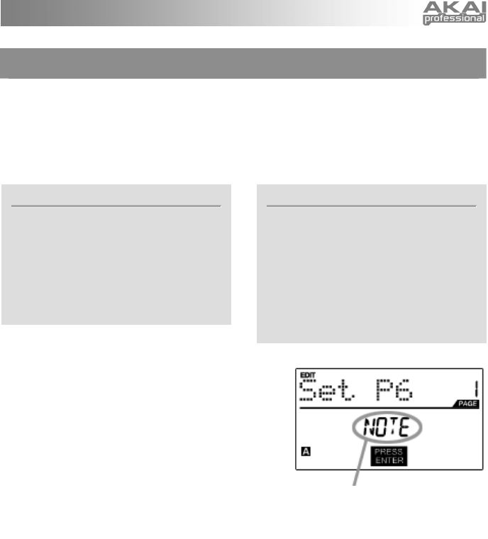
NOTE....................................................................................................................................... 6
NOTE AFTERTOUCH (Channel Pressure).............................................................................. 6
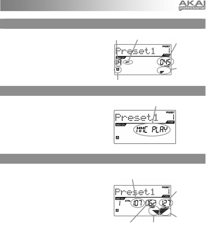
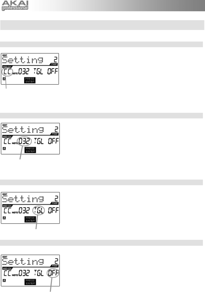
CONTROL CHANGE ............................................................................................................... 6
CONTROL AFTERTOUCH...................................................................................................... 7
MIDI MACHINE CONTROL COMMAND (MMC)...................................................................... 7
PREVIEWING.......................................................................................................................... 7
ABOUT MODES ............................................................................................................................. 8
PRESET MODE.............................................................................................................................. 9
PAGE 1 – LOAD PRESET....................................................................................................... 9
PAGE 2 – SAVE/COPY PRESET ............................................................................................ 9
PAGE 3 – NAME PRESET ...................................................................................................... 9
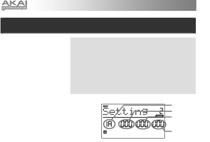
EDIT MODE .................................................................................................................................. 10
EDIT MODE PARAMETERS .......................................................................................... 11
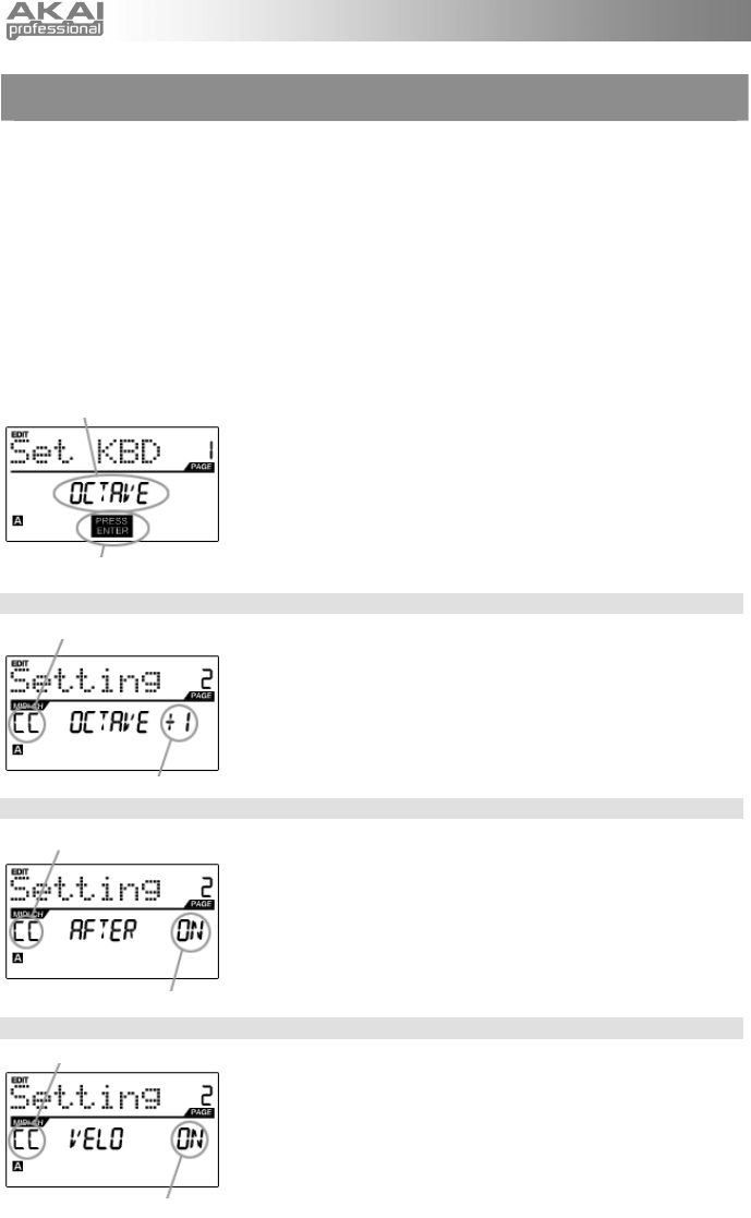
EDITING THE KEYBOARD ................................................................................................... 12
KEYBOARD OCTAVE .................................................................................................... 12
KEYBOARD AFTERTOUCH .......................................................................................... 12
KEYBOARD VELOCITY ................................................................................................. 12
EDITING THE PADS ............................................................................................................. 13
NOTE PARAMETERS .................................................................................................... 14
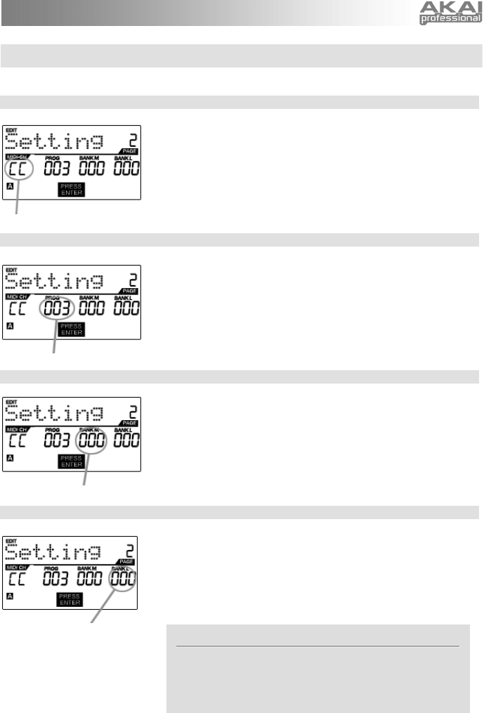
PROGRAM CHANGE PARAMETERS ........................................................................... 15
EDITING KNOBS................................................................................................................... 16
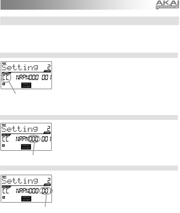
CONTROL CHANGE PARAMETERS ............................................................................ 17
AFTERTOUCH PARAMETERS...................................................................................... 18
INCREMENT/DECREMENT PARAMETERS ................................................................. 19
EDITING BUTTONS .............................................................................................................. 20
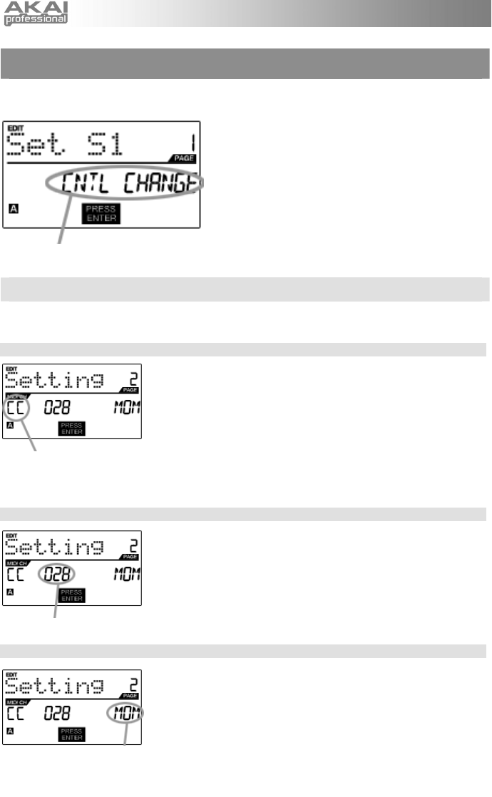
CONTROL CHANGE PARAMETERS ............................................................................ 20
PROGRAM CHANGE PARAMETERS ........................................................................... 21
EDITING THE ARPEGGIATOR............................................................................................. 22
ARPEGGIO PARAMETERS – TYPE, RANGE, BUTTON MODE................................... 23
ARPEGGIO PARAMETERS – GATE, SWING ............................................................... 24
EDITING NOTE REPEAT ...................................................................................................... 25
NOTE REPEAT BUTTON MODE ................................................................................... 26
NOTE REPEAT PARAMETERS – GATE, SWING ......................................................... 26
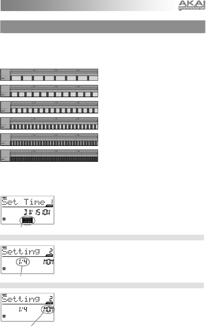
EDITING TIME DIVISION ...................................................................................................... 27
DEFAULT TIME DIVISION ............................................................................................. 27
BUTTON MODE ............................................................................................................. 27
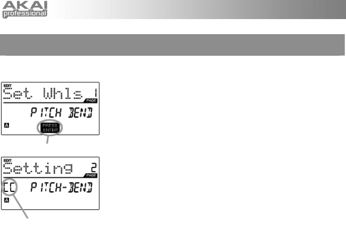
EDITING THE PITCH BEND WHEEL.................................................................................... 28
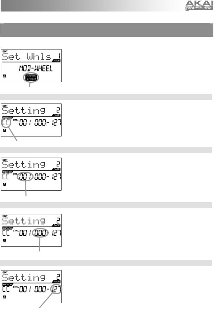
EDITING THE MODULATION WHEEL.................................................................................. 29
EDITING TRANSPORT CONTROL....................................................................................... 30
EDITING TAP TEMPO........................................................................................................... 30
EDITING SUSTAIN PEDAL INPUT ....................................................................................... 31
EDITING EXPRESSION PEDAL INPUT................................................................................ 32
GLOBAL MODE ........................................................................................................................... 33
KILL MIDI – Page1................................................................................................................. 33
MIDI COMMON CHANNEL – Page 2 .................................................................................... 33
LCD CONTRAST – Page 3.................................................................................................... 34
PAD SENSITIVITY – Page 4 ................................................................................................. 34
PAD VELOCITY CURVE – Page 5 ........................................................................................ 34
PAD THRESHOLD – Page 6 ................................................................................................. 35
KEYBOARD TRANSPOSITION – Page 7.............................................................................. 35
MIDI CLOCK – Page 8........................................................................................................... 35
TAP TEMPO AVERAGE – Page 9......................................................................................... 35
SAVE GLOBAL – Page 10..................................................................................................... 36
SYSEX TX – Page 11............................................................................................................ 36
VERSION – Page 12 ............................................................................................................. 36
PROGRAM CHANGE MODE ....................................................................................................... 37
PROG CHANGE (Program Change) ..................................................................................... 37
PROG+BANK (Program Change with Bank Change)............................................................ 37
FREQUENTLY ASKED QUESTIONS .......................................................................................... 38
TROUBLESHOOTING.................................................................................................................. 39
TECHNICAL SPECIFICATIONS .................................................................................................. 40
CONTACT INFORMATION .......................................................................................................... 40