Quick Start Reference Guide
Refer to Product Safety Manual for Safety Statements
Complete Owner’s Manual available online
The switching operation of this
microwave oven can cause voltage
fluctuations on the supply line. The
operation of this oven under unfavor-
able voltage supply conditions can
have adverse effects. This device is
intended for the connection to a power
supply system with a maximum
permissible system impedance Zmax
of 1.1 Ohm at the interface point of
the user’s supply. The user has to
ensure that this device is connected
only to a power supply system which
fulfills the requirement above. If
necessary, the user can ask the public
power supply company for the system
impedance at the interface point.
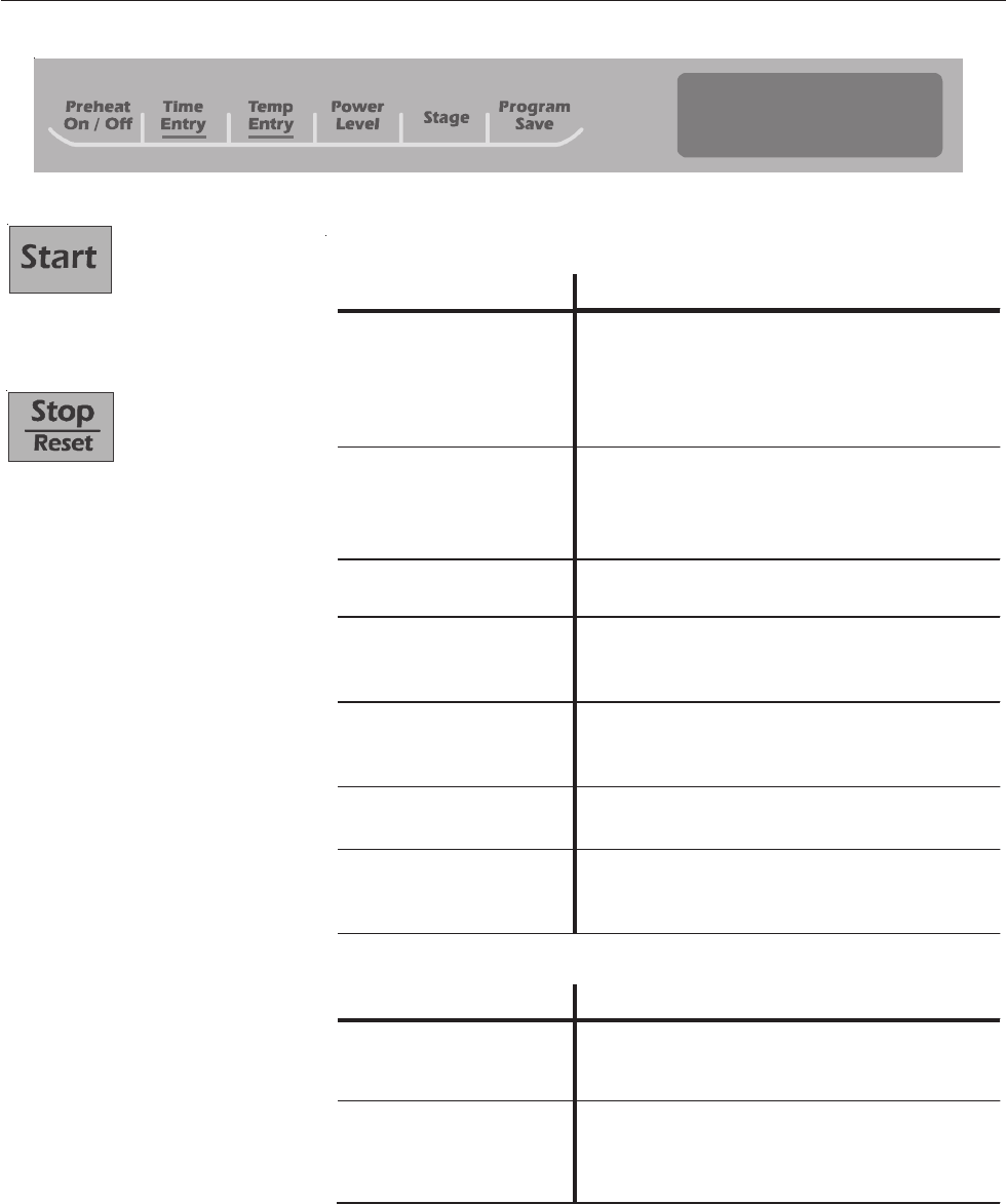
So...how do I use it?
Manual Operation
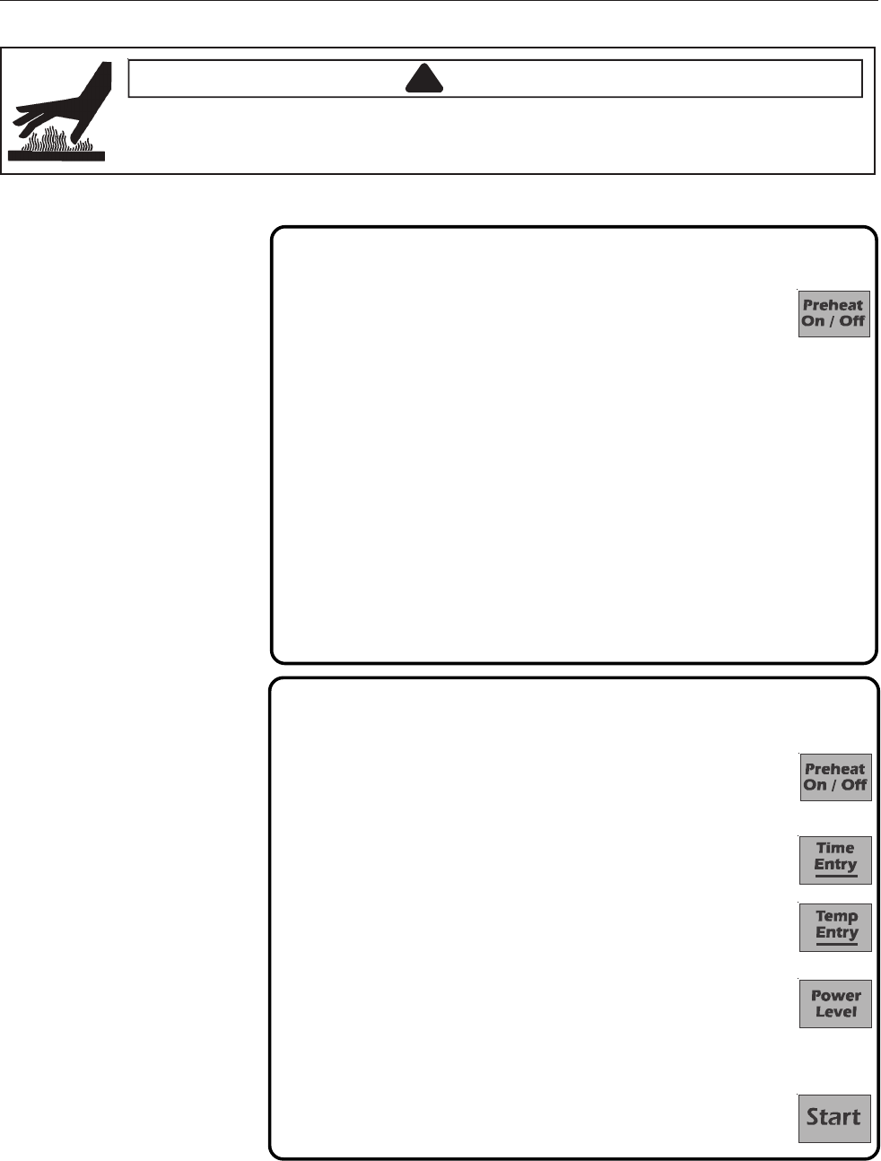
To cook food using a specific entered time and power level.
1. Press Preheat On/Off pad to start the oven.
• Oven Preheating 450°F (230°C) displays with Oven Preheating flashing.
(example of 450°F (230°C) shown
2. Oven reaches preheat temperature.
• Signal sounds and Ready 450°F(230°C) displays. (example of 450°F (230°C) shown)
3. Press Time Entry pad.
• Enter desired cooking time by using numeric keypad.
4. Press Temp Entry pad if cooking temperature differs from preheat temperature.
• Enter the new temperature.
5. Press Power Level pad.
• Press numeric key pad for desired level. Press numeric key pad again to
set power level to 100%.
• For a lower microwave power, press pads 1 (for 10%) through 9 (for 90%).
0 turns off the microwave power and cooking is by convection only.
6. If stage cooking is desired, press STAGE pad and repeat steps 3, 4, and 5.
• Up to 4 different stages can be programmed.
7. Press the Start pad to begin the cooking cycle.
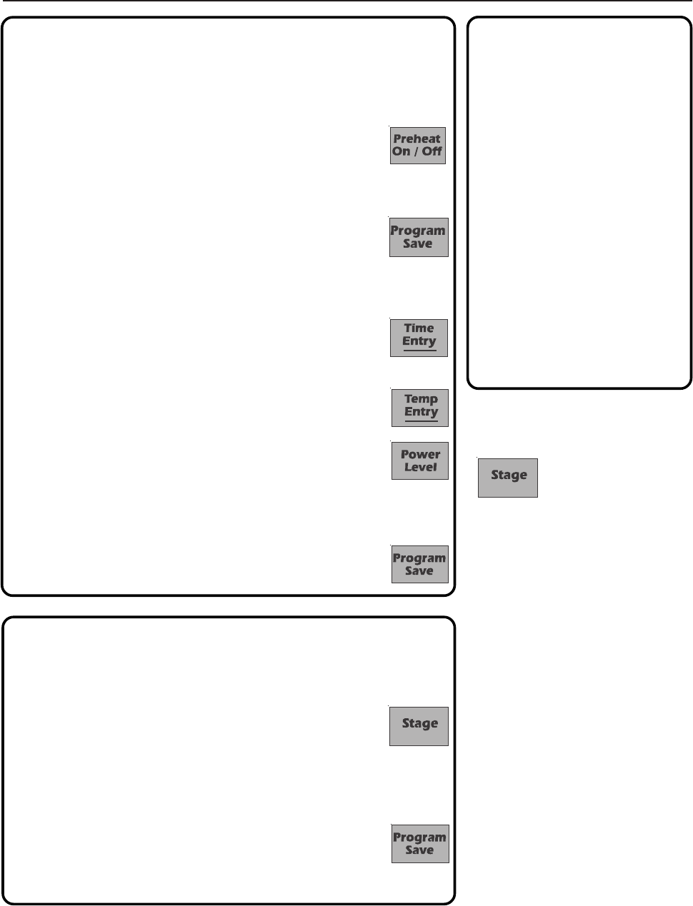
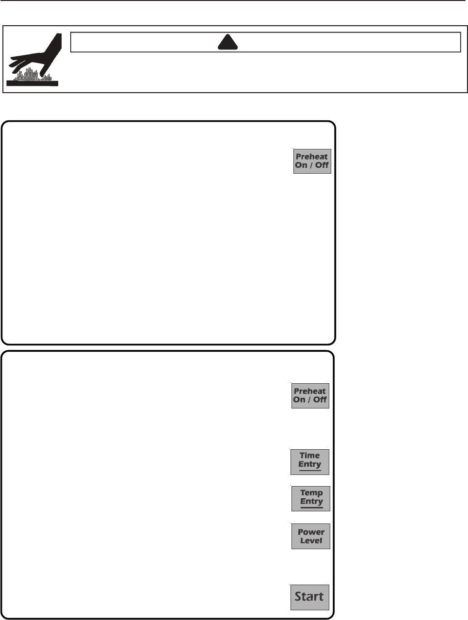
Programming Items
1. Oven must be ON.
• Press Preheat On/Off.
• Oven Preheating 450°F (230°C) displays wit
h Oven Preheating flashing.
(example of 450°F (230°C)
2. Oven reaches preheat temperature.
• Signal sounds and Ready 450°F (230°C) displays with Ready flashing.
(example of 450°F (230°C) shown)
3. Press Program Save pad.
4. Press pad to be programmed or reprogrammed.
5. Press Time Entry pad to program amount of cooking time.
• The total microwave cooking time (all stages combined) is 20 minutes.
6. Press Temp Entry pad to program the cooking temperature.
• Enter desired temperature by using numeric pads.
7. Press Power Level pad to program level of microwave power.
• Press numeric key pad for desired level. Press numeric key pad again to
set power level to 100%.
• For a lower microwave power, press pads 1 (for 10%) through 9 (for 90%).
0 turns off the microwave power and cooking is by convection only.
8. Press Stage pad.
• Enter cook time, temp and power level as in steps 4. 5 and 6.
• To enter another cooking stage for that pad, press Stage pad again. Up to
four different stages can be programmed.
9. Press the Program Save pad to save the program and changes.
N
OTE: To di
scard changes, press Stop/Reset pad before pressing Program
Save pad.
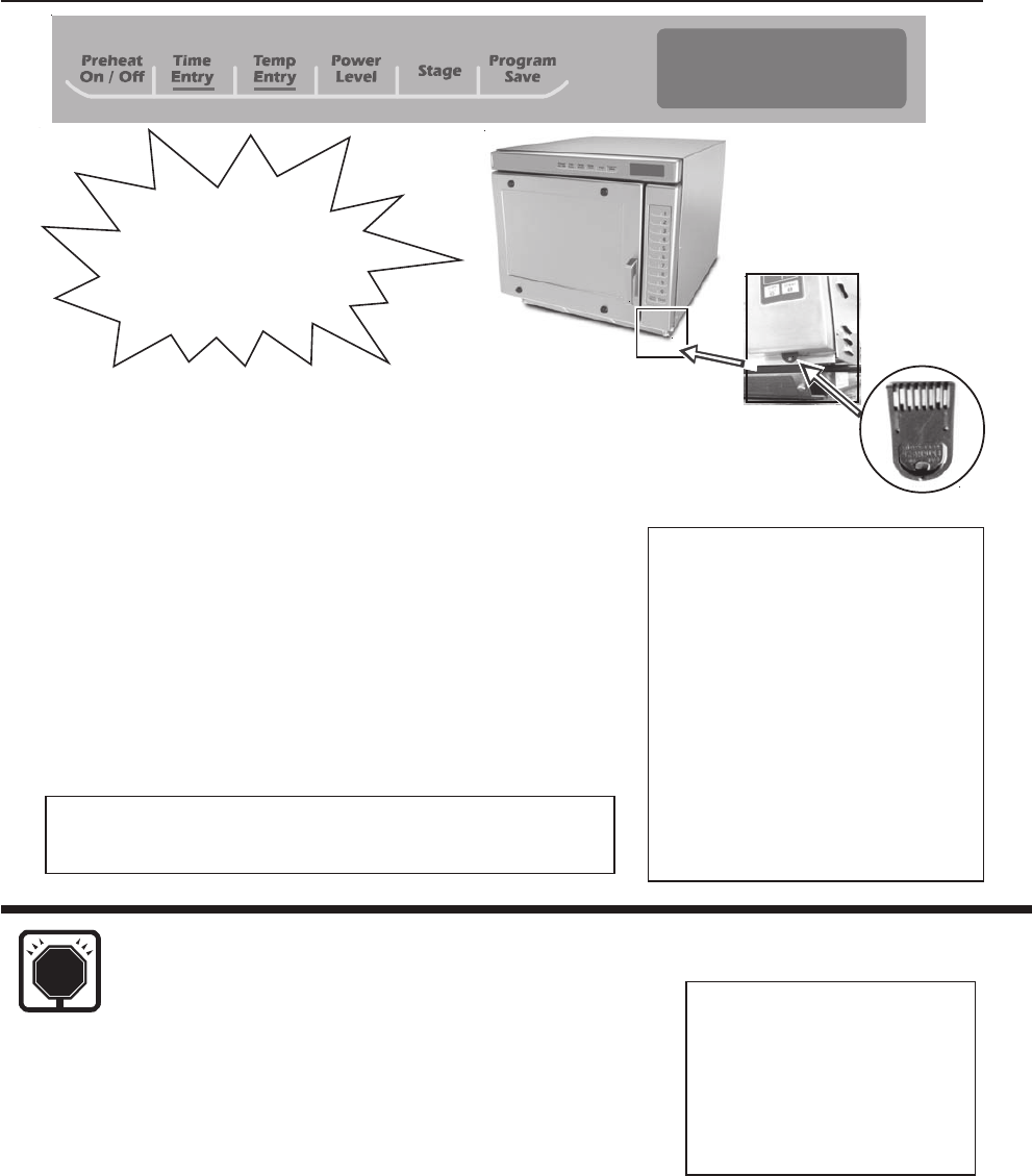
Programming
Preheat Setting
The factory default preheat setting
is 450°F (230°C). To program the
preheat setting oven must be ON:
1. Press Program Save pad.
2. Press Temp Entry pad.
3. Enter desired temperature by
using the numeric key pads.
4. Preheat temperature is changed.
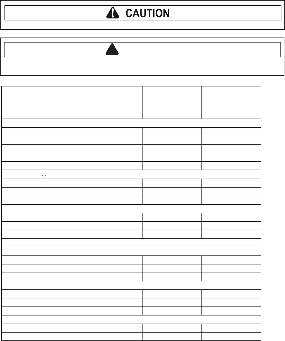
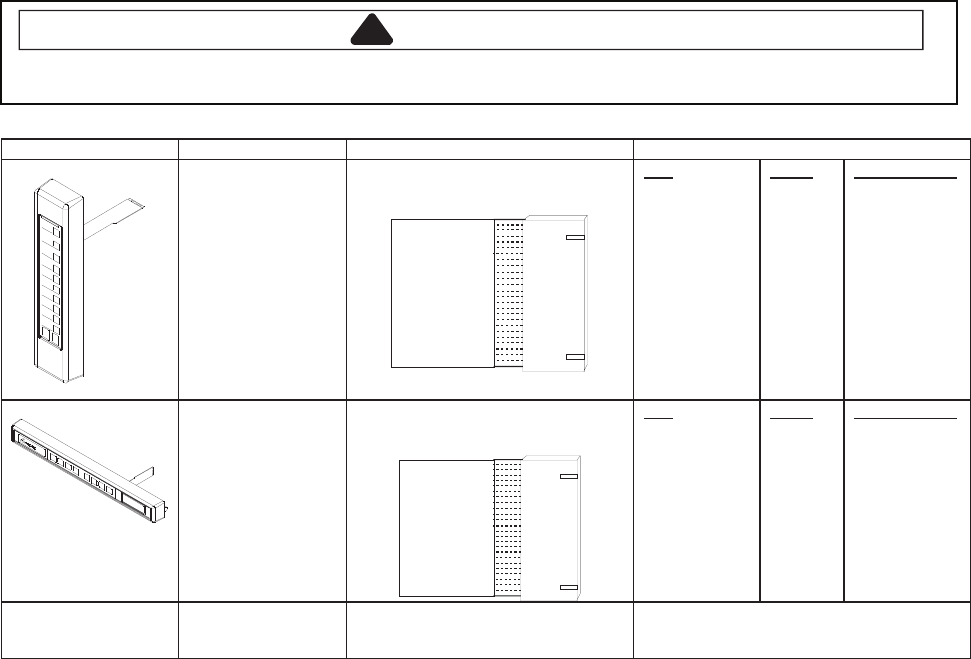
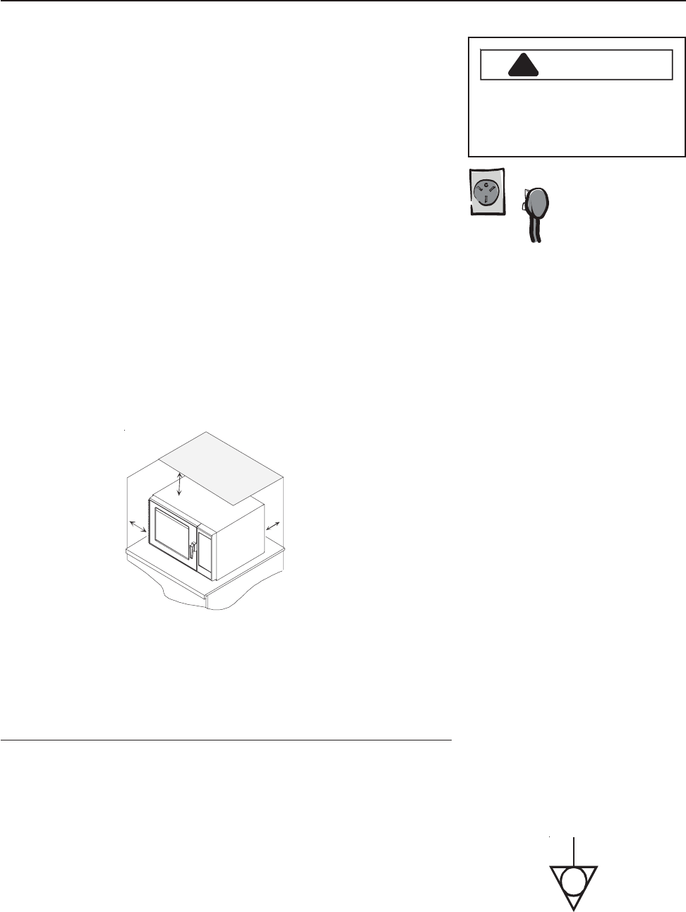
Oven Wall Clearances
A—For North American (UL/CSA) models, allow at least 2” (5.1 cm) of clearance around top of
oven. For International (50 Hz) models, allow at least 7” (17.8 cm) of clearance around top of
oven. Proper air flow around oven cools electrical components. With restricted air flow, oven
may not operate properly and life of electrical parts is reduced.
B—Allow at least 2 9/16” (6,5 cm) between air discharge on back of oven and back wall.
C—Allow at least 1 1/4” (3 cm) of clearance around sides of oven.
C
A
B
Preprogrammed
Pads
To cook food using preprogrammed
cooking sequences.
1. Open oven door and place food
in oven. Close door.
2. Press desired pad.
3. Oven begins to cook.
4. At end of cooking cycle oven
beeps and shuts off.
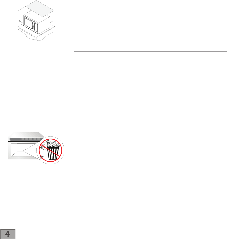
No popcorn